Woodhaven 6015-578DRO: Digital Readout Retrofit for 576-578 User Manual
Browse online or download User Manual for Tools Woodhaven 6015-578DRO: Digital Readout Retrofit for 576-578. Woodhaven 6015-578DRO: Digital Readout Retrofit for 576-578 User Manual
- Page / 2
- Table of contents
- BOOKMARKS
Summary of Contents
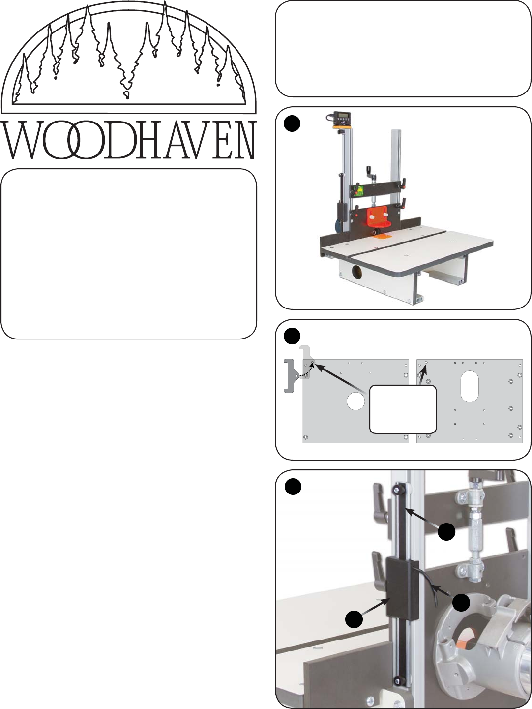
BEFORE BEGINNING Identify and verify that you have all the parts listed. Read thru the instructions at least once, familiarizing yourself with the pa
ATTACH 6015A TO ROUTER PLATEAttach the DRO Mount (6015A) to back of the router plate of your Horizontal Router Table, following one of the next two in
Related products and manuals for Tools Woodhaven 6015-578DRO: Digital Readout Retrofit for 576-578
 (2 pages)
© 2020, manymanuals.com. All rights reserved. | 2.570 s |
 Manymanuals.com
 Manymanuals.de
 Manymanuals.fr
 Manymanuals.it
 Manymanuals.pl
 Manymanuals.cz
 Manymanuals.es
 Manymanuals-pt.com
Comments to this Manuals